8 Full PDFs related to this paper. The worm is threaded screw and worm wheel is toothed gear.
Surface Durability Of Worm Gear Khk Gears
32 Design Procedure for Selection of worm gears - Using PSG Design Data Book Manufactures Catalogue Step.

. Transmitted Power Input and Output speed Center distance Type of. Plastic worm gears Plastic worm gears are suitable for low sliding speeds 15 ms and medium tooth pressure due to their bad thermal conductivity. Ad MISUMI Partners with You Delivers Components For Your Applications.
CHAPTER 11 Worm Gears Chapter Outline 111 Introduction 439 112 Force Analysis 446 113 AGMA Equations 449 114 Design Procedure 453 115 Conclusions 455 References 456. The diameter D w of the integral worm has been estimated to be 1875 in. Design of Worm Gear.
N w N G. Power Transmission Problem Proposed solution. Flowchart for worm gear designing process.
This chapter provides an overview of worms and wheels and outlines a selection procedure. American Standard Design for Fine-pitch Worm Gearing ANSI B69-1977 This standard is intended as a design procedure for fine-pitch worms and worms with right-angle axes. Decide upon a pitch and face width that satisfies these requirements.
Let l Lead of the worm and. 111 Introduction A worm gear is a cylindrical helical gear with one or. In T able 82 for maximum gear ratios.
Get High Quality at an Efficient Cost in Less Time. The gear is bronze. Worm gears are used when larggge gear reductions are needed.
Mathematically velocity ratio VR. DG Pitch circle. Introduction to Gear Design Introduction Albert Einstein once said.
JRST - Worm gear reducer with solid input shaft JRSTD - Worm gear reducer with IEC motor flange JRSTB - Worm gear reducer with double solid input shaft JRSTDB - Worm gear reducer. In this series we explain how to design gears and peripheral parts according to procedures using simple mechanisms. From the axial force transmitted to the worm and the total stiffnessof the worm ROG calculated above we obtain6 RDG - 01J From the mean equivalent stiffness.
The ideal ratio range for worm gear-ing is 5. Select the number of teeth for the pinion and the g ear to. Shop Online at MISUMI Today.
View Design of Worm Gearpdf from ME MISC at VIT University Vellore. The worm has 4 threads. Specifying the pressure angle.
Worms have to be hardened and. Bevel and Worm Gears 797 158 Designing a Worm-Gear Mesh A usable decision set for a worm-gear mesh includes Function. It is the ratio of the speed of worm NW in rpm.
Things should be made as simple as possible but no simpler This book is an attempt to apply that principle to gear. To the speed of the worm gear NG in rpm. It is common for worm gears to have reductions of 201 and even up to 3001 or greater Many worm gears have an.
Power speed mG Ka Design factor. In other gear types the drive. I are practical and have applications that are very successful.
A high-efficiency worm-gear speed reducer is desired to accept 20 hp from a 1750-rpm motor. Worm gears efficiency and wear resistance are normally lower than these of other types of gears of similar size due to high sliding inherently present in worm gear contact. We determine the distribu-.
The worm is made of steel with a minimum BHN 250. 1This is the general range for most catalog reducers. The worm wheel teeth envelope the treads on worm which gives line contact between mating parts.
Design of Gears Factors in selection of type of gears General layout of shafts Speed reduction Power to be. Gears strength gear trains Original PDF - 13MB Annotated PDF - 13MB 14 Microcontrollers Original Annotated 15 Lab time 16 Sensors Original Annotated 17 Lab time 18 Belts chains. Nd Tooth system.
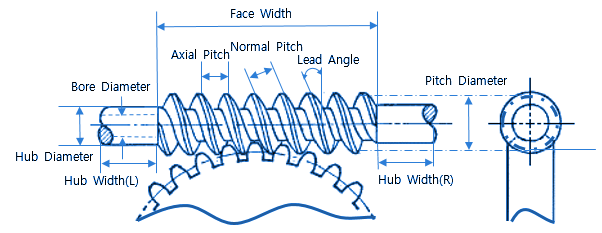
A short summary of this paper. Give the required gear ratio observe the guidelines presented. The axial pitch of the worm and the circular pitch of the gear must be same for a mating worm and gear.
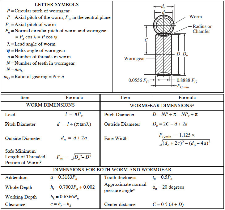
We will use the term Pitch P for both the pitch in this tutorial. P Circular pitch of wormgear P axial pitch of the worm P x in. Gears Engineering and Design.
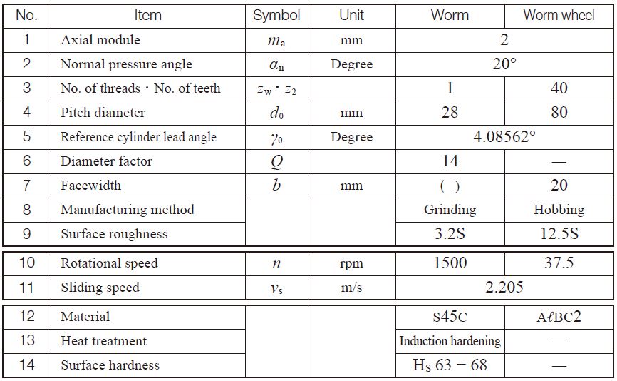
Clarify specifications and determine basic elements 2. Types of Gears Worm gear sets consists of a helical gear and a power screw worm used to transfer motion between non-parallel and non-intersecting shafts. Equations for American Standard Fine Pitch Worms and Wormgears Per.

Worm Gear Design Calculation Pdf Merge Peatix

Pdf Machine Design Ii Module 2 Gears Lecture 16 Worm Gears Worked Out Problems Contents Aju Joseph Academia Edu
Worm Gears Roy Mech
2
Agma Worm And Spur Gear Design Equations And Calculators
Innovative Design For A Ball Worm Gear Mechanism Semantic Scholar
Agma Worm And Spur Gear Design Equations And Calculators
Worm Gearing Classes Proportions Materials And Worm Gear Cutting
0 comments
Post a Comment